Premium E-Book readers these days (Kindle Oasis, Kobo Forma) are sporting an asymmetric design and physical page turn experience. This design makes for a great one-handed reading experience. Both these products are positioned at a premium price point, in excess of $200. Since I was otherwise happy with my Kobo Glo HD, I decided to mod it to add physical page turn buttons!

Full details on the mod are below.
 Now if we momentarily short out the LEDs corresponding to a particular X-Y location, we can fake a touch at this location. So to fake a touch on the left edge, we need to short out two LEDs, one in the middle of the long edge, and one on the left side of the short edge. For a touch on the right side, we need to short out the same LED on the long edge, but one on the right side of the short edge.

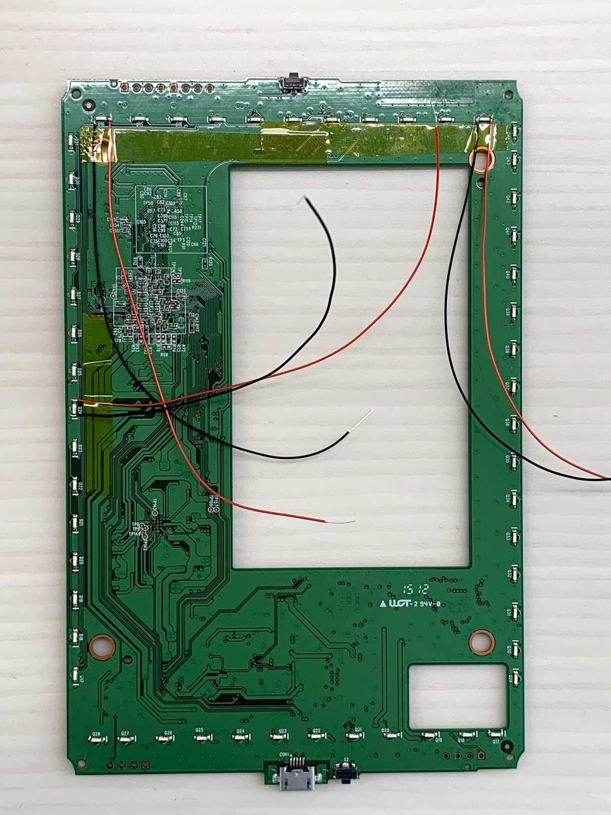
On the other side of the motherboard, I saw the string of LEDs corresponding to the X and Y axes, to which I soldered a few wires:

I did discover that you need to actuate both the X and Y axes simultaneously to register a touch. So if the X axis is actuated first, and then the Y, then it doesn't register a touch. So I needed to find a way to actuate both axis simultaneously for my final implementation. I could either use dual pole switches, but I didn't have any at hand, and was worried about non-simultaneous contact. As a cleaner solution, I wired both buttons to transistors, which short out two LEDs depending on which button is pressed (so button 1 activates transistors which short out middle-Y and left-X LED and button 2 activates transistors which short out middle-Y and right Y-LED). To drive the base of the transistors, I tapped the battery positive supply as well.

I then wired this circuit on a protoboard, and it worked as expected.


Full details on the mod are below.
Architecture
The stock reader SW responds to touches on the screen edge for turning pages forward/backward. Since there are no (known) hooks/API for the SW, the simplest way of turning pages (without actually touching) is to fake touches on the screen edge. The underlying Linux OS on Kobo E-Readers is fairly open, and it is easy to fake touches by recording the input event, and playing it back. With this, it is possible to turn pages with a simple Linux commands. Using this, the folks at mobileread forums have developed ways to remotely turn pages over WiFi. However this relies on keeping the Wi-Fi awake, and so is a battery hog, which isn't great for an E-Reader.
At first I tried looking into talking with the main processor via UART or I2C, but even this was too complicated requiring a dedicated MCU. I then thought of a more direct way, of actuating the touch screen at the page turn locations.
The Kobo Glo HD, like many e-readers uses an optical touch screen. The optical screen relies on a string of LEDs on two sides of the screen, which create a X-Y light field, which is picked up by photoreceptors on the opposite sides. Placing a finger on the screen interrupts the light at a particular X-Y location, which is detected by the digitizer chip.
Putting it together
I decided to try this out, since it seemed simple enough. The back of the Glo HD can be pryed apart relatively easily, and removing the motherboard can be separated removing four screws plus a bunch of connectors.
On the other side of the motherboard, I saw the string of LEDs corresponding to the X and Y axes, to which I soldered a few wires:
I then put back the ereader, and connected the wires to some switches to try it out. As the video below shows, it works beautifully 😀
I did discover that you need to actuate both the X and Y axes simultaneously to register a touch. So if the X axis is actuated first, and then the Y, then it doesn't register a touch. So I needed to find a way to actuate both axis simultaneously for my final implementation. I could either use dual pole switches, but I didn't have any at hand, and was worried about non-simultaneous contact. As a cleaner solution, I wired both buttons to transistors, which short out two LEDs depending on which button is pressed (so button 1 activates transistors which short out middle-Y and left-X LED and button 2 activates transistors which short out middle-Y and right Y-LED). To drive the base of the transistors, I tapped the battery positive supply as well.

I then wired this circuit on a protoboard, and it worked as expected.

Designing a case
Now that everything was electrically complete, I decided to put it all together. At first I thought of designing a full top case replacement to be 3D printed, but got bored halfway through. Then I decided to go with a simple case to hold my circuit, which would function as a grip. The sidewall of the Kobo has a slight taper and I matched the taper on my case with this, so that the front face was flush. I didn't have any black filament, so I printed it with white ABS. I then attached it to the side of the top case of the Kobo with some ABS glue (ABS dissolved in acetone) + a couple of screws for strength.

(in retrospect, the design of the case was too boxy, and I should have probably made something more ergonomic for gripping. I may redo it when I get some black filament)
Success!
Lastly, I assembled everything together, screwing my circuit board into standoffs on the case, and attached button caps. Since the white looked distracting compared with the black Kobo, I painted it black. The black does look a bit different from the black of the Kobo, and the finish isn't great, but as seen in the video, it works perfectly, and I can comfortably use my Kobo with one hand.

Final thoughts
I have always wondered why physical buttons are not standard issue on ereaders. After all, they can't be too expensive to add. I guess this is primarily driven by marketing and to differentiate the premium range (Oasis, Forma). As shown in my project, it can be done in less than few dollars.
I did cut a few corners with this project. Some improvements in the mechanical design are needed (buttons are too far away, grip shape is not ergonomic), which I may improve at a later time. The ultimate goal is to complete my custom top case design, so that the buttons naturally blend into the rest of the product.
Electrically, a simple improvement is to add a switch to reverse the connection of the left and right transistor gates, allowing to swap the forward-backward mapping of the buttons. A more ambitious goal is to stick in a low power MCU, allowing for more tricks, such as a slideshow/autoplay mode, remote page turn etc.
Clearly, there is a lot of room to build on this idea, and I plan to pursue some of these in future, but for now for a weekend project, I'm quite satisfied with the way the mod turned out 😃


